Installation of TRIGENERATION SYSTEM 1560 kW
Continental Automotive Romania, Timisoara
The contribution to the powerplant is: 1.393,94 kWp
1. Introduction
The main activity of Continental Automotive Romania is production of electronic devices and research and development for automotive area.
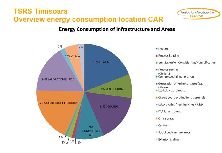
In 2018, the Company’s total electricity consumption was 40500 MWh and total gas consumption was 8800 MWh. In our location is implemented ISO 50001 standard for Energy Management system and the strategy and for increase the efficiency of energy consumption.
The main target is reduction of energy consumption in the main areas of consumption: heating, cooling and circuit board production.
Another target is to assure the continuity of electricity supply due to often disconnections from the city grid.

2. DEFINITION OF PROJECT No.3_TRIgeneration system
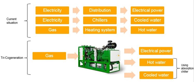
Tri-generation is the process whereby a single fuel source, natural gas (in our case), is used to produce both electrical and thermal energy (cooling and heating).
Remarks:
- Usually fossil-fuelled power plants have an efficiency of 33%. TSR implementation use actively 90% of the gas energy to produce electrical energy and heat & cold
- TSR CHP protect the production lines and critical utilities in case of city line electricity breakdown.
3. ADVANTAGES
Efficiency Benefits
CHP requires less fuel to produce a given energy output and avoids transmission and distribution losses that occur when electricity travels over power lines. The average efficiency of fossil-fuelled power plants is 30-35 %. Average CHP efficiency is 60-80% some systems could reach 90%.
Environmental Benefits
Because less fuel is burned to produce each unit of energy output and because transmission and distribution losses are avoided, CHP reduces emissions of greenhouse gases and other air pollutants. Usually electricity distribution loss is around 4.5%.
Economic Benefits
CHP can save facilities considerable money on their energy bills due to its high efficiency, and it can provide a hedge against electricity cost increases.
Reliability Benefits
Unreliable electricity service represents a quantifiable business, safety, and health risk for some companies and organizations. CHP is an on-site generation resource and can be designed to support continued operations in the event of a disaster or grid disruption by continuing to provide reliable electricity.
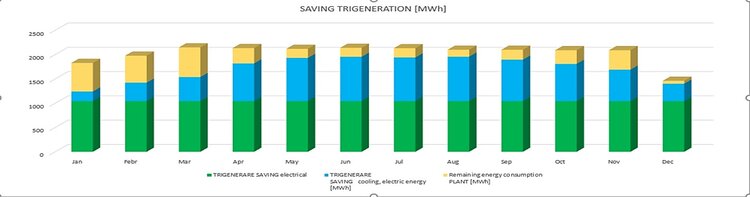
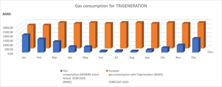
4. EFFICIENCY ANALYSIS
Gas consumption: before and after TRIGENERATION implemented
5. DESCRIPTION OF THE TRIGENERATION PROJECTS
The profile of this investment is thermal and electrical energy production in trigeneration, the finished products being: hot water, cool water and electricity. The trigeneration plant are connected to the existing electrical and thermomechanical installations of the company debiting electricity and thermal energy (hot water, cold water) to Continental consumers.
Trigeneration has become an efficient solution for the future for the production of cold water (cold water) in the production areas, offices and warehouses, both in the field of service provision and in the industrial one. During the trigeneration process, the cool water is obtained from the heat energy through a chiller.
Cogeneration on natural gas offers the promise of significant energy savings compared to the traditional technology for producing electricity in thermal power stations on gas or coal. The main economy comes from the local, simultaneous use of electricity and heat. However, thermal energy is not required all year long. The solution is trigeneration: adding an absorption chiller to the cogeneration plants. The absorption chiller uses the heat agent produced by cogeneration to produce cool water with temperatures similar to the ones produced by a classic chiller, considered a conventional technology. By adding a chiller with absorption to the cogeneration group the thermal agent can be used also during the summer, being able to ensure a functioning near 100% of the installation. The use of thermal energy for the production of cool water has many advantages: it allows the continued use of the cogeneration group as a more efficient electricity supply solution than the classical solution; the absorption chiller takes over part of the cooling task of the building, thus reducing the electrical consumption of the classic chillers installed in parallel and thus reducing the load on the overloaded electrical network during the summer.
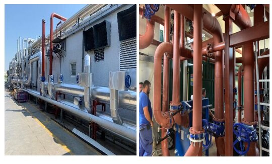
The methane gas is taken from the methane gas distribution network. By burning it in the gas engine, the electric generator produces electricity. For cooling the gas engine, the chemically treated water delivered from an automatic water treatment station located in the Continental Automotive Romania is used, the hot water thus obtained is delivered to the beneficiary, at a temperature of 90 ° C. The combustion gases discharged from the heat engine are used in a gas-water plate exchanger, with the water outlet temperature also rising to 90 ° C; The circulation of the primary hot water agent is carried out in a closed circuit, the heat transfer being carried out by means of a plate heat exchanger with a capacity of 1700 KW.
With the help of cooling systems, absorber type, part of the hot water is converted into cool water up to 6 ° C. The cooled water is delivered to Continental being used in the production process, to the air conditioning of office and warehouse spaces. In winter, more hot water will be delivered, cool water in summer, the installation allows the combined operation of hot and cold water depending on the CAR needs.
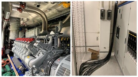
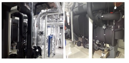
The installation of energy installations are mounted inside containers, a closed enclosure, as follows:
- The internal combustion heat engine driving an electric generator;
- Electric generator with nominal power of 1560 kW;
- The hot water pumping station has 3 pumps, equipped with inverters for automatic adjustment of pump speed depending on the thermal and electrical load:
- Cooling water production facility – 2 absorption chillers, cooling water temperature inlet / outlet: 12/7 ° C.
- Each chiller is equipped with a pumping group consisting of two pumps, which have inverters for automatically adjusting the pump speed depending on the thermal and electrical load, as follows:
- Welded plate heat exchanger;
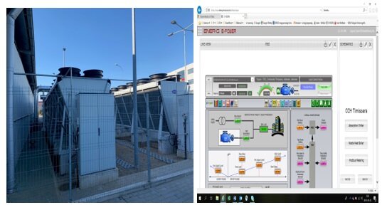
- Cooling system for internal combustion heat engine and absorption chillers – adiabatic temperature coolers;
- The electrical cabinets that ensure the power supply of these equipment.
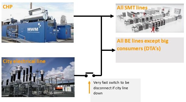
6. ELECTRICAL IMPLEMENTATION
- CHP power all the production busbars and normally is connected in parallel with city network. The extra generator power is transfer to Conti electrical network using switch K;
- If city network power down occur the switch is fast disconnected, and generator will power only the production area and some utilities;
- CHP capacity allow to continue the production in SMT lines and finalize the processes on BE lines.
- When the city power is restoring automatically the generator is synchronize with the city line and the switch will be close automatically.
7. POWER INTERRUPTION FROM CITY GRID_COST AVOIDANCE
CHP/generator is connected to production lines busbars and to the mandatory utility (exhaust, compress air, technological water).
- For PCB production/SMT lines even very short power interrupt create direct scrap (19 lines*20 PCB’s*30 € = 11400 €) and quality risks;
- All the machines and traceability system after power interruption need to be restart (average 30 minutes production impact);
- Power interrupt create often damage for production equipment and infrastructure equipment fault;
- After power interruption, in assemble line all the product in the line need to be check/review at analyze station.
Direct impact: scrap reduction, production efficiency increases and reduce quality risks.
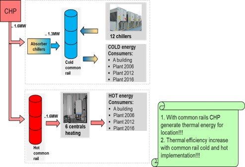
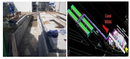
8. THERMAL CIRCUIT CONNECTION
Cold water: Hot Water:
Production capacity: Production capacity:
CHP: 1.3MW CHP:1,7 MW
Chillers: 7.3MW With Burner: 5,8MW
Free cooling (winter): 1,7MW
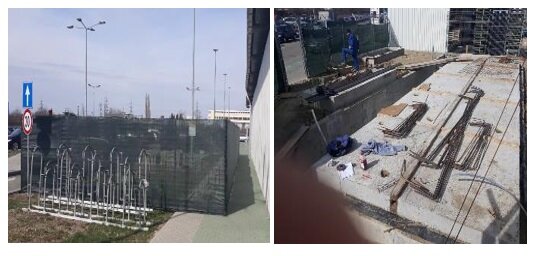
9. IMPLEMENTATION PHASES
A. Foundation
B. Installation
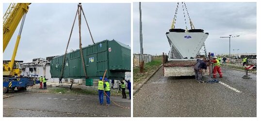
1.5 MW engine
Connection to cold circuit
C. Final implementation
10. PROJECT TEAM CONTINENTAL AUTOMOTIVE ROMANIA
Dr. Petru Demian
Eng. Petronel Lungu
Eng. Cosmin Vacariuc
Eng. Alexandru Cozmescu
Eng. Ciprian Ceauranu
Eng. Daniel Popescu
11. Contribution to the VPPP
- Energy management 1292 MWh
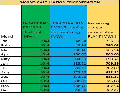
- Trigeneration: 12.528 MWh energy + 2.907,25 MWh heat
- Total saving: 16.727,25 MWh
PVPPP= QVE x η / τCS
Where:
PVPPP – Energy Saving accounted in the Virtual Power plant
QVE – The full energy saving, meaning the basis of the calculations
η – average powerplant efficiency
τCS – annual peak hours of the power plant
The contribution to the powerplant is: 1.393,94 kWp